Business License

What Is a Wire Cutting Machine and How Does It Actually Work
A wire cutting machine removes metal by spark erosion rather than by a rotating cutter. A thin wire electrode runs vertically through the workpiece while the table carries the part beneath it, and a discharge across a gap of a few hundredths of a millimetre does the cutting. No cutting force ever reaches the part, which is why a 1.5 mm rib holds its shape in a way a 6 mm end mill cannot manage.
That single property explains why the process keeps a fixed place in toolrooms and precision shops. Sections too thin to mill, too hard to turn, or too sharp-cornered to grind are ordinary work for it. The wire cutting machine working principle is worth understanding because it decides which jobs belong here and which belong on a mill.
1. What a Wire Cutting Machine Actually Does
An aerospace bracket came back from a machining centre with a 0.08 mm bow along a 180 mm internal rib. The locating fixture had already been signed off, so the error travelled into three downstream assemblies before anyone traced it back. The shop had quoted the part as a milling job and lost eleven working days to rework.
The same geometry on a wire cutting machine takes a single setup and leaves no bending force behind. The wire never touches the work, because between the wire and the workpiece sits a gap filled with deionised water. Metal is removed atom by atom as the generator fires.
Most shops arrive at the process from the opposite direction. They buy a machine for one hard job, then discover the corner radii, the straightness and the repeatability it holds without operator attention.
2. The Wire Cutting Machine Working Principle Step by Step
The wire cutting machine working principle rests on one physical event repeated thousands of times a second. A pulsed voltage breaks down the dielectric in the gap, the discharge channel vaporises a microscopic volume of metal, and the debris is flushed away before the next pulse arrives.
Follow one cycle and the whole machine becomes readable. Wire unwinds from a supply spool, passes a tension brake, threads through an upper guide, crosses the work zone, exits through a lower guide, and is wound onto a take-up reel. Deionised water floods both guides and the kerf. The controller then advances the table by a few microns and waits for the gap to recover before firing again.
Any account of the wire cutting machine working principle has to mention what the servo is actually chasing. It is not position but gap voltage. When the gap widens the voltage climbs and the table speeds up; when debris bridges the gap the voltage collapses and the table backs off.
Every feed rate you read on a screen is a side effect of that loop. Suzhou Excellence Intelligent Technology Co Ltd walks buyers through the same wire cutting machine working principle as four settings that decide everything downstream: wire tension, flush pressure, pulse energy, and servo gain. Get the first two wrong and the wire breaks, while the last two wrong leave a finish that never settles.
3. Machine Layout and the Wire Path
The mechanical layout follows from the erosion process rather than from conventional machine tool practice. Because the wire cutting machine working principle needs a stable gap rather than a rigid tool, there is no spindle to stiffen, but there is a wire path that must stay straight within microns over several hundred millimetres.
Most machines share the same set of sub-assemblies. Each one carries a specific job in keeping the gap stable.
| Sub-assembly | Function | Typical figure |
|---|---|---|
| Wire transport | Feeds, tensions and recovers the electrode | 8-20 N tension |
| Upper and lower guides | Locate the wire relative to the table | 0.02-0.05 mm gap |
| X-Y table | Moves the workpiece under the wire | 300-1,000 kg load |
| Dielectric system | Flushes the kerf and insulates the gap | 5-50 kilo-ohm-cm |
| Pulse generator | Sets discharge energy and frequency | up to 200 sq mm per minute |
Guide wear is the quiet failure mode in this layout. A guide that has opened by 0.01 mm will still cut, but the kerf widens at the bottom of a tall part and the taper appears on the last inspection rather than the first.
4. Wire Cutting Machine Wire Types and What Each One Costs You
The wire cutting machine wire types in common supply fall into four families, and the choice drives both cut speed and consumable spend. Diameter matters as much as material, because a 0.25 mm wire removes roughly twice the kerf volume of a 0.1 mm wire over the same path length.
| Wire type | Diameter range | Typical use |
|---|---|---|
| Plain brass | 0.15-0.30 mm | General steel and aluminium work |
| Zinc-coated brass | 0.20-0.30 mm | Faster roughing on thick sections |
| Molybdenum | 0.05-0.20 mm | Fine features and small radii |
| Tungsten | 0.02-0.10 mm | Micro work below 0.5 mm features |
Comparing wire cutting machine wire types on price alone misleads, because a cheap wire that breaks twice a shift costs more than a coated one that runs clean. Brass accounts for most consumption in a general shop since it balances conductivity against price and fails predictably under tension. Coated wire earns its premium on cuts above roughly 100 mm thick, where improved flush shortens the roughing pass by a visible margin.
The wire cutting machine wire types at the small end change what geometry becomes possible. Molybdenum and tungsten enter the picture when feature size drops, and a 0.05 mm wire can produce a 0.06 mm inside radius that no 0.25 mm brass wire will reach.
One practical note applies across all wire cutting machine wire types. A wire that has sat in a humid store for a season will break at the tension roller before it reaches the guides, so stock rotation matters as much as grade selection.
5. Wire Cutting Machine Travel Range and Part Envelope
The wire cutting machine travel range sets a hard boundary on what the machine accepts, and it is easy to misread because the advertised axis stroke is not the usable envelope. Guides, clamps and the wire path all consume part of that travel.
| Axis | Common specification | What it limits |
|---|---|---|
| X axis | 350-600 mm | Part length plus clamping stock |
| Y axis | 250-450 mm | Part width plus clamping stock |
| Z axis | 200-400 mm | Workpiece height between guides |
| Taper | plus or minus 15 degrees | Draft and clearance angles |
Reading a wire cutting machine travel range correctly means subtracting the clamping allowance before believing a quotation. A 400 mm X stroke does not accept a 400 mm part, because 40-60 mm at each end goes to clamps and to letting the wire clear the slug. That brings practical capacity down to roughly 300 mm.
Suzhou Excellence Intelligent Technology advises buyers to measure the largest part they expect within two years rather than the largest part on the bench today. A machine bought against today's job tends to run out of wire cutting machine travel range about the time the second customer arrives, and the wire cutting machine travel range is the one specification that no upgrade can extend afterwards.
6. Taper Work on a Wire Cutting Machine
Taper cutting is where the fourth and fifth axes earn their place, and where the wire cutting machine travel range interacts with the angle you can hold. The upper guide tilts relative to the lower guide, so the wire leans through the workpiece and produces a draft angle in a single pass.
A machine rated at plus or minus 15 degrees usually holds that angle up to a stated workpiece height. At 100 mm the angle may hold, but at 250 mm the same machine might manage 5 degrees before the wire deflects. The taper rating is therefore a pair of numbers, and a single figure in a brochure tells half the story.
Shops cutting ejector pin holes and clearance angles rely on this capability to avoid a second setup. The trade-off is speed, since a leaning wire travels a longer path through the same section.
7. Accuracy and Finish on a Wire Cutting Machine
Positioning accuracy on a modern machine sits near plus or minus 0.005 mm, but the figure that matters in production is repeatability across a full shift. Thermal drift in the dielectric tank moves the part more than servo error does, which is why temperature control belongs in the specification conversation.
Surface finish arrives in passes. The first cut leaves 0.5-1 mm of stock in a tall section and a finish near Ra 3.2 micron. Two to four trim passes follow, each removing a few hundredths of a millimetre, until the surface settles between Ra 0.4 and Ra 1.6 micron.
Excellence Intelligent Technology puts the practical point plainly. A shop that quotes a single-pass finish on a 150 mm part is quoting a rework ticket.
8. Where a Wire Cutting Machine Stops Paying Off
The process is not a general-purpose replacement for milling, and treating it as one is how shops end up with slow cycle times. It cuts a path, not a pocket, so a large open cavity belongs on a milling machine.
Three conditions push work away from wire erosion. The material must conduct electricity, so ceramics and most polymers are out. The feature must be reachable by a continuous wire path, so blind internal cavities need a start hole first. Volume of removed material must stay modest, because erosion rate rarely exceeds 200 square millimetres per minute however the generator is set.
Where a part is thin, hard, sharp-cornered or dimensionally tight, the economics flip and wire erosion wins on the first attempt. That is the boundary the wire cutting machine working principle draws for you.
9. Two Wire Cutting Machine Cases in Practice
Two jobs show how the decision plays out when tolerance is tight and geometry is awkward.
A die shop was cutting 12 identical core inserts from hardened D2 at 60 HRC. Milling the 0.8 mm corner radii caused chatter and left a 0.03 mm mismatch between adjacent inserts, which appeared as a visible step in the moulded part. Moving the corner profiles onto a wire cutting machine with 0.2 mm brass wire and four trim passes held the mismatch under 0.008 mm across the set. Cycle time rose by 40 percent, but the assembly no longer needed hand fitting.
A second shop used 0.05 mm molybdenum wire to cut 0.15 mm wide slots in a 12 mm tall stainless plate. The first pass held slot width variation to 0.006 mm, a figure the shop had previously reached with grinding.
10. Wire Cutting Machine Questions Buyers Ask
10.1 Can a wire cutting machine cut non-conductive material?
No, because the process relies on electrical discharge, so the workpiece must conduct enough current to sustain the spark across the gap. Ceramics, glass, most engineering polymers and unfired composites cannot be cut this way. Some shops attach a conductive starting plate to initiate a cut on a borderline material, but the body of the part still has to carry current through the kerf. For a conductive ceramic such as silicon carbide with a metallic binder, run a sample test before committing a production batch, because dielectric behaviour varies enough to change the pass count.
10.2 How thick a workpiece can a wire cutting machine handle?
It depends on the Z axis between guides, which typically runs 200-400 mm on a mid-size machine. Advertised figures assume ideal flushing, and above roughly 150 mm the flush reaches the bottom of the kerf less effectively, so wire breakage rises while the cut rate falls. Thick sections call for coated wire, higher tension and a lower servo gain. Our team recommends a test cut at the actual production height rather than extrapolating from a thin sample that ran clean at a fraction of the height.
10.3 What determines the surface finish on a wire cutting machine?
Finish is set by the number of trim passes and the energy of the final one, not by the wire alone. A roughing pass leaves a recast layer and a finish near Ra 3.2 micron. Each trim pass removes a few hundredths of a millimetre and lowers that figure, with three or four passes reaching Ra 0.4 micron. Running fewer passes on a tall part leaves taper and a rougher surface at the bottom of the kerf, so pass count should follow section height rather than shop habit, which is why Suzhou Excellence Intelligent Technology quotes pass counts against measured height.
10.4 Does a wire cutting machine need a separate programming system?
Most machines ship with a controller that accepts two-dimensional geometry directly, so simple profiles can be programmed at the console. Complex work with taper, multiple starts or slug retention benefits from a CAM package that simulates the wire path and generates the pass sequence. The handover point matters more than the software brand, because a post-processor that misreads the machine's taper convention produces parts out of tolerance while the simulation still looks correct on screen. Ask for a test part with a known taper before accepting the post.
Recently Posted
-
Wire Cutting Machine Terms You Will Meet in a Supplier Quotation
November 18, 2026A quotation for a wire cutting machine arrives as a table of terms, half of which describe the machine and half of which describe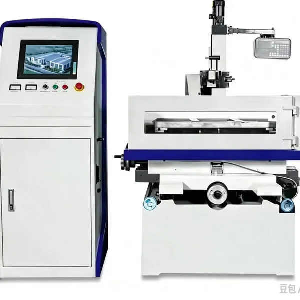 Read More
-
Wire Cutting Machine vs Sinker EDM: How the Two Processes Differ
November 17, 2026Both processes remove metal with a spark, and both run with the workpiece submerged in a dielectric. Past that point they diverge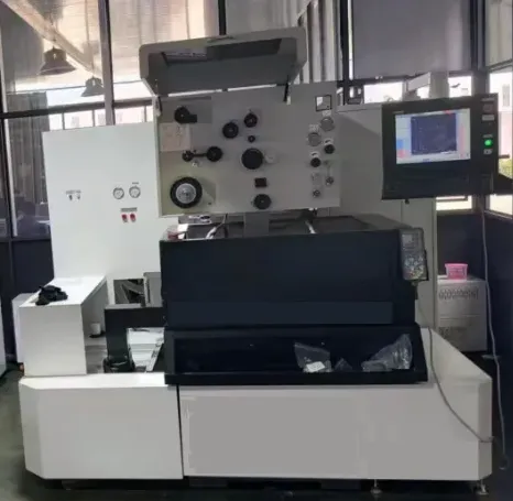 Read More
-
Small Hole EDM Drilling vs CNC Drilling for Small Diameter Holes
November 17, 2026Below about 1 mm diameter in hardened steel, a twist drill stops being a cutting tool and becomes a breaking tool. The small hole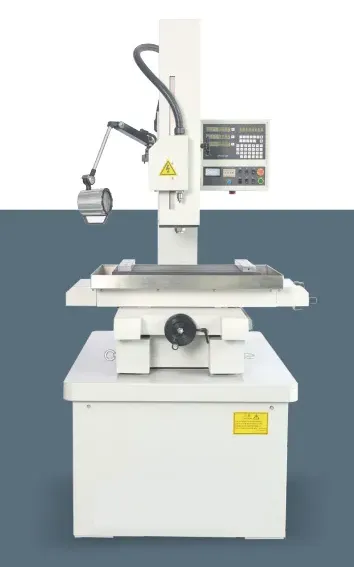 Read More
-
A Practical Introduction to Small Hole EDM Drilling Machines
November 16, 2026A small hole EDM drilling machine sinks narrow holes through hard metal by spark erosion, using a rotating tubular electrode fed t Read More

Contact Us
Recommended Products
-
 CNC Boring Machine Horizontal Boring and Milling MachineNegotiableMOQ: 1 Unit
-
Slow Wire Cutting Machine Slow Speed Wire Cutting Machine Made in ChinaUS$ 5500 - 1500000MOQ: 1 Unit
-
Double Column Vertical Lathe Cnc Vertical Lathe Vertical Turning and Boring MillNegotiableMOQ: 1 Unit
-
Cnc Vertical Lathe Vertical Turning and Boring MillNegotiableMOQ: 1 Unit
-
Cnc Vertical Five-Axis Milling Machining Center Made in ChinaUS$ 48000 - 100000MOQ: 1 Set

-
Cnc Edm Drilling Machine Automatic Wire Feed Made in China 0.15-6.0mmUS$ 5500 - 1500000MOQ: 1 Unit
-
Sevro Moto Wire Cut Machine Cnc Wedm With Larger Taper Made in ChinaUS$ 5500 - 1500000MOQ: 1 Unit
-
Cnc Milling Machine Made in ChinaUS$ 28000 - 100000MOQ: 1 Set
-
VMC(vertical Machining Centre) CNC Milling MachineUS$ 28000 - 100000MOQ: 1 Set
-
Semi-Automatic Hole Drilling EDM Machine With 0.2-6 mm Electrode, 7 MPa Cooling, 3 kW MotorUS$ 3500 - 500000MOQ: 5 Sets


-
High-Speed Hole Drilling EDM Machine With 12,000 Rpm Electrode Rotation, 1-10 mm Range, IP54US$ 3500 - 500000MOQ: 5 Sets
-
Automatic Hole Drilling EDM Machine, 30 A Pulse Power, 600 mm X-Axis Travel, PLC ControlUS$ 3500 - 500000MOQ: 5 Sets
-
Hole Drilling EDM Machine for Aerospace Turbine Blades, 0.3-2 mm Holes, 5-Axis ControlUS$ 3500 - 500000MOQ: 5 Sets
-
Hole Drilling EDM Machine With 1-Year Warranty, On-Site Technical Training, Standard CompliantUS$ 3500 - 500000MOQ: 5 Sets
-
Hole Drilling EDM Machine, 400 x 300 mm Worktable, 0.01 mm Positioning Accuracy, 220VUS$ 3500 - 500000MOQ: 5 Sets
-
Hole Drilling EDM Machine With 12-Month Warranty, Online Technical Support, Free Remote DiagnosisUS$ 3500 - 500000MOQ: 5 Sets
-
CNC Hole Drilling EDM Machine With 5-Axis Servo Control, 0.3-3 mm Electrode, 380VUS$ 3500 - 500000MOQ: 5 Sets
-
CNC Hole Drilling EDM Machine With 0.005 mm Resolution, 500 mm Z-Axis Stroke, 24 V ControlUS$ 3500 - 500000MOQ: 5 Sets
-
Hole Drilling EDM Machine for Mold Cooling Channels, 0.5-3 mm Holes, 400 mm DepthUS$ 3500 - 500000MOQ: 5 Sets
-
CNC Engraving Machine With Factory Test Report and Standard Compliant, 220V 2.2kW, 12-Month Warranty and Setup SupportNegotiableMOQ: 1 Unit